Would you like to make this site your homepage? It's fast and easy...
Yes, Please make this my home page!
• http://www.geocities.com/tyala.geo/x2-dxfm2.htm • http://yala.freeservers.com/x2-dxfm2.htm • http://www.angelfire.com/in2/yala/x2-dxfm2.htm
Synthesizers, Music & Television © T. Yahaya Abdullah
FM Spectrum Graphs
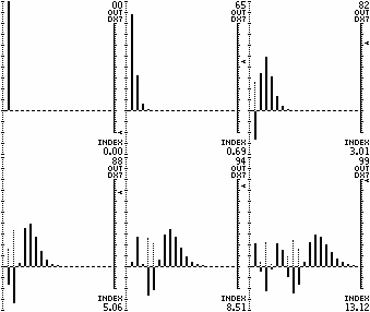
Bessel Graph
The graph plots the Amplitudes for each Order of Sideband (calculated using Bessel functions significant to the nearest percent). For FM, this is only "one side" of the spectrum because FM will have Sidebands on each side of the Carrier (Carrier = Order Zero). Also, any reflected Sidebands (phase inverted) need to be taken into account.
 Note - Negative amplitudes are also shown as positive dotted lines (This gives a better picture of the harmonic strengths generated). Negative amplitudes denote phase inversion.
The graph is scaled for a DX-7 range. The DX-7 Modulator Output is shown in the upper-right corner. The equivalent Modulation Index is shown in the bottom right-corner. The slider-indicator on the right is scaled for a DX-7 Modulator Operator (just another tool to help visualise the process).
FM Spectrums
If we disregard amplitudes, there are basically 2 types of Series; (a) with coincidental reflected sidebands, and (b) with non-coincidental reflected sidebands (reflected sidebands are phase inverted). If we examine the amplitudes, the effect of the reflected sidebands depends on the modulation amount (ie how much the sidebands spread out) as well as the Carrier frequency "C" (as "C" is the centre point of the modulation). The modulation frequency "M" determines the separation of the sidebands.
The spectrums displayed are M:C=1:16, M:C=1:8, M:C=1:1, M:C=2:1 and M:C=3:1 (from left to right). The first four graphs have coincident reflected sidebands while the last does not. Inverted phase frequencies are shown as dotted lines. Output values are for DX-7 series of synths.

- M:C = 1:16 ~ This is a good example of the FM spectrum without the interference of reflected sidebands. It shows the basic spread of sidebands as modulation is increased. C=16 is high relative to M=1. In this case, LS#16 (the 16th lower sideband) is at F1, LS#17 is at F0 (ie silent) and LS#18 is inverted at F1 (LS#18 is the first refected sideband). The sidebands spread out on both sides of "C" symmetrically. The effect of reflected sidebands (ie LS#18 onwards) only occurs at high modulation amounts.
- M:C = 1:8 ~ This example also shows the symmetrical spread but has some interference of coincident reflected sidebands. C=8 is medium relative to M=1. In this case, LS#8 is at F1, LS#9 is at F0 (silent) and LS#10 is inverted at F1 (LS#10 is the first reflected sideband). The sidebands spread out symmetrically up to a point at moderate modulation amounts where the effect of reflected sidebands (ie LS#10 onwards) occurs.
- MC = 1:1 ~ This example shows the dramatic effect of the interference of coincident reflected sidebands. C=1 is low relative to M=1 (a very popular ratio for string sounds). In this case, LS#1 is at F0 (silent) and LS#2 is inverted at F1 (LS#2 is the first reflected sideband). The effect of reflected sidebands (ie LS#2 onwards) occurs at low modulation amounts.
- M:C = 2:1 ~ Another example of the effect of the interference of coincident reflected sidebands. C=1 is low relative to M=2 (a ratio for wind instruments perhaps). In this case, LS#1 is inverted at F1 (the first lower sideband is already reflected). The effect of reflected sidebands (ie LS#1 onwards) occurs at low modulation amounts.
- M:C = 3:1 ~ This is a good example of the effect of non-coincident reflected sidebands. C=1 is low relative to M=3 (perhaps for wood percussion sounds). In this case, LS#1 is inverted at F2 (the first lower sideband is already reflected) but is not coincident with another sideband. The effect of reflected sidebands (ie LS#1 onwards) occurs at low modulation amounts.
For M:C = 4:1 or 5:1 or 6:1 or 7:1 etc, the amplitudes would be the same as M:C=3:1 but the separation of the sidebands would be different. In general, series with non-coincident reflected sidebands are easier to predict.
• FM Synthesis - HTML Version ; Printer/Text Version
• Go to DX Spectrum Amplitudes
• Back to Main Page
~ END OF DOCUMENT ~
 Note - Negative amplitudes are also shown as positive dotted lines (This gives a better picture of the harmonic strengths generated). Negative amplitudes denote phase inversion.
